Setting up Cisco ACI From Scratch

This Cisco ACI article describes the first few things you will do when getting ACI Fabric components in your datacenter.
Cisco ACI 3.2 version was used to try the stuff described below
So let’s see what we have here:
Get Your Gear
In this one, we will get three APIC controllers, four Leafs and two Spines to build simple ACI and few 2060 switches for OOB management:
- 3x APICs APIC-CLUSTER-M2 – APIC Controller Medium Configuration (Up to 1000 Edge Ports)
- 2x Spines N9K-C9364C – Nexus 9K ACI & NX-OS Spine, 64p 40/100G QSFP28
- 2x SFP Leafs N9K-C93180YC-EX – Nexus 9300 with 48p 10/25G SFP+ and 6p 100G QSFP28
- 2x Copper Leafs N9K-C9348GC-FXP – Nexus 9300 with 48p 100M/1GT, 4p 10/25G & 2p 40/100G QSFP28
- 2x Catalyst 2960 OOB management switches
You need to cable Leaf and Spines in-between properly to form CLOS topology from the image below with 40G or 100G optics. Each Spine, Leaf and APIC controller needs to be connected to non-ACI OOB management network. You need then to connect redundantly APIC controllers to two Leafs with 10G optics and start the APIC initialization and fabric discovery.
Cable The Thing
Spines are all ports 40G/100G so you Choose your ports as you like, and for Leafs, each of them has last 6 ports 40G/100G so use one of those to connect to each Spine and you have your Leaf’n’Spine.
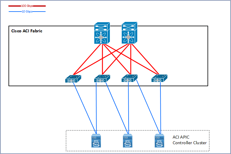
ACI Fabric with APIC