Category: Software Defined Datacenters

ACI MultiPod – Enable Standby APIC

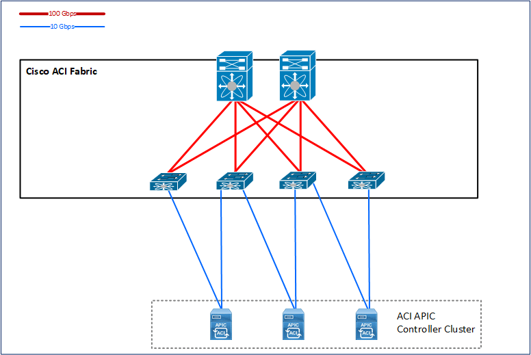
APIC Controller Cluster

You actually need three APIC controller servers to get the cluster up and running in complete and redundant ACI system. You can actually work with only two APICs and you will still have a cluster quorum and will be able to change ACI Fabric configuration.

Loosing One Site

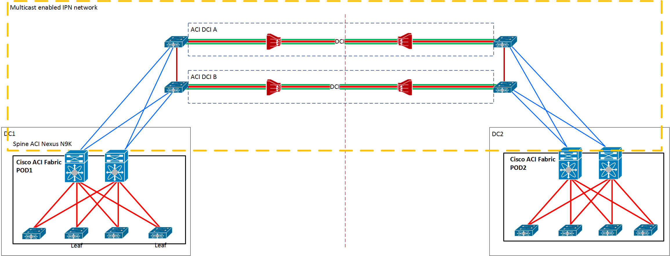
In the MultiPod, those three controllers need to be distributed so that one of them is placed in the secondary site. The idea is that you still have a chance to keep your configuration on one remaining APIC while losing completely primary site with two APICs. On the other hand, if you lose secondary site, two APICs in the first site will still enable you to do configuration and management of ACI Fabric as nothing happened.

Losing DCI Interconnect

The second type of MultiPod fail is when you lose DCI (datacenter interconnect). In that case, both sites will keep working but will alert that the other side is down. The secondary site with one APIC will be in read-only mode and the primary site will be fully functional with two remaining APICs on that site. If some changes are made on the primary site, those changes will be replicated to the third controller on the secondary site when DCI recovers and configuration relating site B POD will be then pushed to POD 2 fabric.

DCI issues are not a good time for APIC replacement, just wait for DCI to start working normally and continue to use ACI APIC controllers as before the issues. You will still have the option to manage primary site if DCI fails and after DCI starts working again changes will be replicated to secondary site APICs and Fabric.

Please note that temporary DCI issues are not a good time to replace the APIC. If you are experiencing just a DCI outage the second site still works but it cannot be configured. Think about it, perhaps the best thing to do in this case is not to change the configuration of your fabric on either side while DCI doesn’t get back up and running. That way you are sure your configuration does not affect the MultiPod stability once DCI gets back up and sites start to communicate again.

Setting up Cisco ACI From Scratch

This Cisco ACI article describes the first few things you will do when getting ACI Fabric components in your datacenter.

Cisco ACI 3.2 version was used to try the stuff described below

So let’s see what we have here:

Get Your Gear

In this one, we will get three APIC controllers, four Leafs and two Spines to build simple ACI and few 2060 switches for OOB management:

  • 3x APICs APIC-CLUSTER-M2 – APIC Controller Medium Configuration (Up to 1000 Edge Ports)
  • 2x Spines N9K-C9364C – Nexus 9K ACI & NX-OS Spine, 64p 40/100G QSFP28
  • 2x SFP Leafs N9K-C93180YC-EX – Nexus 9300 with 48p 10/25G SFP+ and 6p 100G QSFP28
  • 2x Copper Leafs N9K-C9348GC-FXP – Nexus 9300 with 48p 100M/1GT, 4p 10/25G & 2p 40/100G QSFP28
  • 2x Catalyst 2960 OOB management switches

You need to cable Leaf and Spines in-between properly to form CLOS topology from the image below with 40G or 100G optics. Each Spine, Leaf and APIC controller needs to be connected to non-ACI OOB management network. You need then to connect redundantly APIC controllers to two Leafs with 10G optics and start the APIC initialization and fabric discovery.

Cable The Thing

Spines are all ports 40G/100G so you Choose your ports as you like, and for Leafs, each of them has last 6 ports 40G/100G so use one of those to connect to each Spine and you have your Leaf’n’Spine.

ACI Fabric with APIC

ACI MultiPod and how to build MultiDatacenter with Cisco ACI

What is MultiPod?

ACI MultiPod was first designed to enable the spread of ACI Fabric inside a building (into two or more Pods), let’s say in two rooms at different floors, without the need to connect all the Leafs from one room to all the Spines in the other room. It was a way of simplifying the cabling and all that comes with building spread CLOS topology fabric stuff.

MultiPod also saves some Leaf ports giving the fact that Pod to Pod connection through Multicast enabled IPN network connects directly to Spines.

Cisco ACI Multi-Pod

People soon realized that MultiPod will be a great solution for a dual site (or more than dual) Datacenter with the ability to have single management with a single ACI Fabric stretched across two or more locations that are connected with an IP connection not too long so that enables RTT latency of less than 50msec with Multicast support. Not too simple but it seems not too demanding for most cases.

What is Cisco ACI?

Hello World

This is an overview of what I think Cisco ACI actually is. It uses some examples from the lab environment to show you how the things look like when you start to work with ACI. There are other articles in the works which will be online soon and which will go in details through the real configuration of ACI and best practices while doing it.

What is this Cisco ACI Fabric?

Cisco ACI is a datacenter network Fabric. It actually means that it is a networking system of more networking L3 switches that have a modified, next-generation OS which enables them to be centrally provisioned and configured through APIC controller to work as one device from access port perspective.

ACI APIC GUI Topology

The view at Cisco ACI APIC GUI where we see complete ACI Fabric Topology

CLOS Topology

Edson Erwin invented this highly scalable and optimized way of connecting network nodes in the 1930s and Charles Clos made the telephone nodes interconnection design using that solution. It was even before we had IP networks. He invented it in order to optimize the architecture of telephony network systems back then.

It was not used in IP based network for last few decades but it experienced a big comeback with new datacenter design in the last few years. It was first invented only for scalability requirements that it solved beautifully. In new datacenter design, CLOS topology of interconnecting network devices scalability is also the first requirement that gets solved, but it also greatly helps with improving resiliency and performance.

In today’s datacenters, CLOS topology is used to create Leaf’n’Spine system of interconnecting Leaf switches (datacenter access switches or ToR switches) together through Spine switches. It is created in a way that each Leaf switch is redundantly connected to all Spine switches directly.

As it is shown in the picture below, in this way, using CLOS topology, we are interconnecting Leaf switches in a way that they always have only two hops between each other and this done redundantly as two hops through each Spine switch. Spines are not directly connected and Leafs are also not directly connected.

CLOS